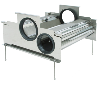
3P Volume filter VF7
Industrial filter
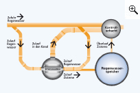
Operating principle
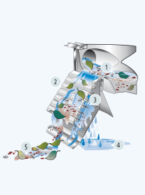
- As water arrives the level builds up and overtops the filter lip, so ensuring it is distributed evenly across the whole width of the filter cascade.
- Pre cleaning through the cascades. Largest dirt particles are led across the primary filter cascades directly to the sewer.
- Pre filtered water then flows over the secondary filter sieve (Mesh size 0,4 x 1 mm). Due to the special mesh structure of the sieve, any dirt falls directly down onto the bottom of the shaft. In case of heavy rainfalls, the filter has more loss, as the water washes away the filtered dirt into the sewer.
- The cleaned water is being absorbed in the lower tank and directed through a tube DN 150 into the storage.
- Dirt goes to the sewer through the shaft.
Technical Data
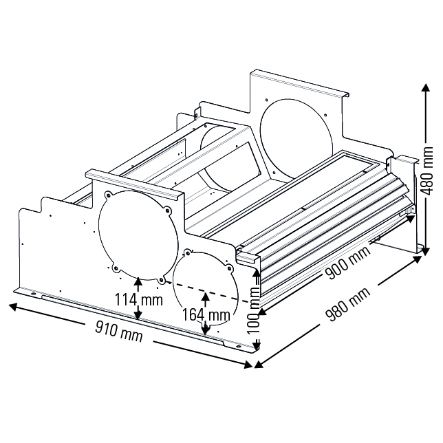
Connectable area: 2433 m²
Maximum Flow Rate Sieve insert: 11 l/sec = 39.6 m³ clean water per hour
Rainwater inlet: 2 x DN 250
Connection inlet: DN 250
Outlet into tank: DN 200
Application
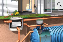
Installation of volume filters in the pre-chute
If the size of the roof surface or the pipe diameters deviate from the specifications, a DIN-compliant installation can be carried out as shown below.