stormwater Treatment system
3P Hydrosystem ® 1000
- Approvals
- Download
Operating Principle
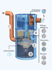
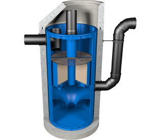
- The rainwater from the area to be drained is introduced at the lower end of the shaft of the rainwater treatment plant, and the water is deflected tangentially by a deflection aid.
- Here, sedimentation of particles, especially of the sand fraction, takes place in a hydrodynamic separator due to turbulent secondary flows in a radial, laminar flow regime. In this way, solids are already retained here and the filters are effectively protected against colmation.
- These are collected via an opening in the lower part of the cleaning shaft in a sludge trap under the system, the sludge trap is sucked out at intervals.
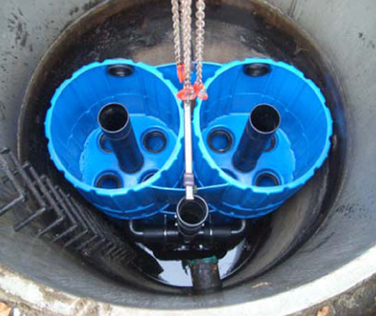
- In the middle of the cleaning shaft there are 4 filter elements, with these filter elements the fines are filtered in the upflow process and a large part of the dissolved pollutants are adsorptively bound, the filter can be backwashed and in case of complete sludge formation it can be easily replaced. The design of the individual filters enables the operator to safely and sustainably maintain the material cycle.
- The clean water is located above the filter elements. It passes through a light-matter barrier (in the event of an accident, larger quantities of oil and gasoline are retained (for example, in the event of an accident), "normally" occurring hydrocarbons are removed in the filter) and then flows through the drain into the seepage system or into the body of water.
Stormwater treatment plant Technical data
Hydraulic flow of the filters when new: min. 12 l/s
Hydraulic flow rate: min. 2.5 l/sSupply and installation of the shaft structure described below for the treatment of precipitation water from traffic, roof and metal roof surfaces. Precast concrete parts corresponding to strength class C35/45 according to DIN EN 206-1 and DIN 1045-2/4 (no exposed concrete)
Manhole structure consisting of:
Base part with socket, Di = 1000 mm, h = approx. 2910 mm, socket according to DIN 4034-1, 2 boreholes with insertion seal for KG/DN200, inlet socket pipe KG/DN200, fall pipe KG/DN200 factory-mounted on shaft structureManhole neck 100/60:
according to DIN EN 1917/4034-1, manhole cover Di = 625 mm (class B)1 piece 3P Hydrosystem factory installed in previously described manhole. We recommend a cover without ventilation.
Heaviest single weight: 2.500 kg
Total weight: 3.000 kg
stormwater treatment plant dimensioning

Stormwater treatment system
3P Hydrosystem ® 1000 roof
for roof areas
Connectable area up to 1.000 m²
Installation in shaft structures up to D = 1.0 m
Stormwater treatment system
3P Hydrosystem ® 1000 traffic
for roof areas
Connectable area up to 750 m²
Installation in shaft structures up to D = 1.0 m
Stormwater treatment system
3P Hydrosystem ® 1000 heavy traffic
for roof areas
Connectable area up to 500 m²
Installation in shaft structures up to D = 1.0 m
Zulassung: DIBt Z-84.2-4
Stormwater treatment system
3P Hydrosystem ® 1000 metal
for metal roofs
Connectable area up to 650 m²
Installation in shaft structures up to D = 1.0 m
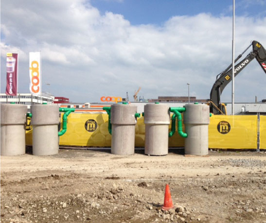
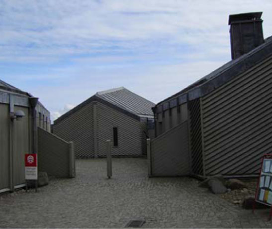
Rainwater treatment system references